Missing injector command
An injector has the expected power feed, but the ECM does not provide the commanded switching or pulse on one output.
An injector or ignition fault is not always caused by the injector, coil, wiring, or engine. A failed output stage inside the ECM, ECU or DME can leave one circuit inactive while the controller still communicates and otherwise appears to operate.
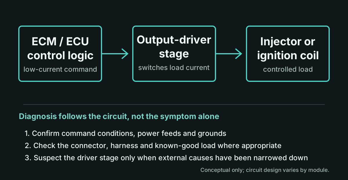
The driver stage becomes a legitimate suspect only after the rest of the circuit and the conditions required for the command have been checked.
An injector has the expected power feed, but the ECM does not provide the commanded switching or pulse on one output.
A misfire or injector/coil circuit fault remains tied to the same controller output after a known-good load is substituted.
Continuity, connectors, power and ground have been checked, yet the expected controller output is still absent or intermittent.
An output can become intermittent with temperature or movement, pointing toward a connection or component fault that needs careful isolation.
One ignition coil is not being switched correctly even though the coil, feed and external circuit have been reasonably ruled out.
Swapping an injector or coil does not move the problem, and mechanical testing does not explain the affected cylinder.
Diagnosis should consider the injector or ignition coil, its power feed and ground, connectors, corrosion, harness opens or shorts, and an overload in the controlled circuit. Mechanical engine faults can also produce a persistent misfire. In some operating conditions the ECM may intentionally withhold an output because a required input or command condition is missing.
Vehicle owners should not pierce wiring or attempt live backprobing without the correct service information and test equipment. A repair shop can usually provide better circuit findings before the module is removed.
The microcontroller generally does not power an injector or ignition coil directly. It sends a low-current command to a semiconductor output stage designed to switch the load current and, depending on the design, monitor or protect the circuit.
That stage may use an integrated automotive driver IC, individual transistors, MOSFETs, IGBTs, or a combination of devices and supporting components. The correct repair depends on the actual board, the surrounding circuit, the damage, and whether suitable parts and test methods are available.
Many modules arrive after normal vehicle diagnosis has already been completed. A short account of those findings is more useful than a symptom alone.
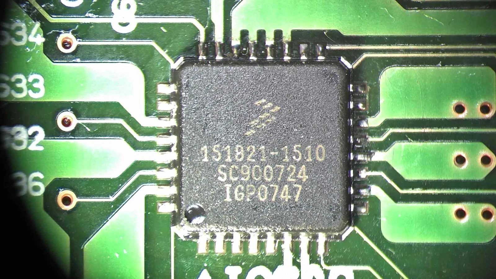
Some Subaru ECM injector-control faults are discussed by the board reference IC608. A related failure can present as a persistent no-pulse or injector-control problem after the injector, power feed, wiring, connector and mechanical causes have been narrowed down.
IC608 is a useful board-level reference, not a diagnosis by itself. Subaru application, ECM part number, affected output and vehicle-side findings still need to be reviewed. The photograph shows the actual device and surrounding board area under the microscope; it does not, by itself, prove how a particular module failed.
For a Subaru no-injector-pulse or persistent misfire inquiry, include the cylinder affected, codes, module number, and the tests that led back to the ECM output.
BMW DME and other ECM repairs can involve output stages, power-supply circuitry, communication circuits, failed discrete components, damaged traces or pads, corrosion, and previous repair damage. Support depends on the exact controller and fault.
The Subaru IC608 example is specific to that board context. It should not be taken to mean that BMW DMEs or other controllers use the same device or fail in the same way.
Full vehicle simulation is not available or appropriate for every ECM. The test scope is explained when that limitation affects the job.
Provide the vehicle and module details, affected injector or coil, codes, and the diagnostic work already completed. We will review whether board-level evaluation is a reasonable next step before you ship the module.